The Reflection of Light
| Reflections at Uncoated
Surfaces | |
| Whenever light is incident on the boundary
between two media, some light is reflected and some is transmitted
(undergoing refraction) into the second medium. Several physical laws
govern the direction, phase, and relative amplitude of the reflected
light. For our purposes, it is necessary to consider only polished optical
surfaces. Diffuse reflections from rough surfaces are not considered here.
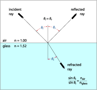
The law of reflection states that the angle of incidence equals the angle of reflection. This is illustrated in the figure below, which shows reflection of a light ray at a simple air/glass interface. The incident and reflected rays make an equal angle with the axis perpendicular to the interface between the two media. | |
| |
| Reflection and
refraction at a simple air/glass interface | |
| Intensity | |
| At a simple interface between two dielectric
materials, the amplitude of reflected light is a function of the ratio of
the refractive index of the two materials, polarization of the incident
light, and the angle of incidence. When a beam of light is incident on a plane surface at normal incidence, the relative amplitude of the reflected light, as a proportion of the incident light, is given by | |
 | |
| where p is the
ratio of the refractive indices of the two materials (n1/n2). Intensity is the square of this
expression. The amount of reflected light is therefore larger when the disparity between the two refractive indices is greater. For an air/glass interface with the glass having a refractive index of 1.5, the intensity of the reflected light will be 4% of the incident light. For an optical system containing ten such surfaces, this shows that the transmitted beam will be attenuated to 66% of the incident beam from reflection losses alone. | |
| Incidence
Angle | |
| The intensity of reflected and transmitted
beams is also a function of the angle of incidence. Because of refraction
effects, it is necessary to consider internal and external reflection
separately at this point. External reflection is defined as reflection at
an interface where the incident beam originates in the material of lower
refractive index (i.e., air in the case of an air/glass or air/water
interface). Internal reflection refers to the opposite case. | |
| External Reflection at a
Dielectric Boundary | |
| Fresnel's laws of reflection precisely describe
amplitude and phase relationships between reflected and incident light at
a boundary between two dielectric media. It is convenient to think of
incident radiation as the superposition of two plane-polarized beams, one
with its electric field parallel to the plane of incidence (p-polarized) and the other with its electric field
perpendicular to the plane of incidence (s-polarized). Fresnel's laws can be summarized in
the following two equations which give the reflectance of the s- and p-polarized
components: | |
 | |
 | |
| In the limit of normal incidence in air,
Fresnel's laws reduce to the following simple equation: | |
 | |
| It can easily be seen that, for a refractive
index of 1.52 (crown glass), this gives a reflectance of 4%. This
important result shows that about 4% of all illumination incident normal
to an air-glass surface will be reflected. In a multielement lens systems,
reflection losses would be very high if antireflection coatings were not
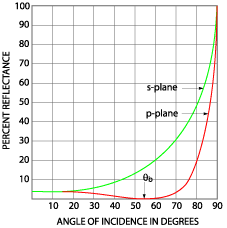
used. The variation of reflectance with angle of incidence for both the s- and p-polarized components, plotted using the formulae above, is shown in the figure below. | |
| |
| External reflection at
a glass surface (n=1.52) showing s- and p-polarization
components | |
| It can be seen that the reflectance remains
close to 4% over about 30 degrees incidence, and that it rises rapidly to
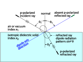
100% at grazing incidence. In addition, note that the p-component vanishes at 56° 39'. This angle,
called Brewster's angle, is the angle at which the reflected light is
completely polarized. This situation occurs when the reflected and
refracted rays are perpendicular to each other (q1+ q
2= 90º ), as shown in the figure below. | |
| |
| At Brewster's angle
the p-polarized component is completely absent
in the reflected ray | |
| This leads to the expression for Brewster's
angle, qB: | |
 | |
| Under these conditions, electric dipole
oscillations of the p-component will be along
the direction of propagation and therefore cannot contribute to the
reflected ray. At Brewster's angle, reflectance of the s-component is about 15%. | |
| Internal Reflection at a
Dielectric Boundary | |
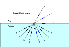
| For light incident from a higher to a lower
refractive index medium, we can apply the results of Fresnel's laws in
exactly the same way. The angle in the high-index material at which
polarization occurs is smaller by the ratio of the refractive indices in
accordance with Snell's law. The internal polarizing angle is 33° 21' for
a refractive index of 1.52, corresponding to the Brewster angle
(56° 39') in the external medium, as shown in the figure
below. | |
| |
| Internal reflection at
a glass surface (n=1.52) showing s- and p-polarized
components | |
| The angle at which the emerging refracted ray
is at grazing incidence is called the critical angle (see the figure
below). For an external medium of air or vacuum (n = 1), the critical angle is given by | |
 | |
| and depends on the refractive index n (l), which is a function
of wavelength. For all angles of incidence higher than the critical angle,
total internal reflection occurs. | |
| Phase Changes on
Reflection | |
| There is another, more subtle difference
between internal and external reflections. During external reflection,
light waves undergo a 180-degree phase shift. No such phase shift occurs
for internal reflection (except in total internal reflection). This is one
of the important principles on which multilayer films
operate. | |
| Interference | |
| Quantum theory shows us that light has
wave/particle duality. In most classical optics experiments, it is
generally the wave properties that are most important. With the exception
of certain laser systems and electro-optic devices, the transmission
properties of light through an optical system can be well predicted and
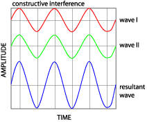
rationalized by wave theory. One consequence of the wave properties of light is that waves exhibit interference effects. Light waves that are in phase with each other undergo constructive interference, as shown below. | |
| |
| A simple
representation of constructive interference | |
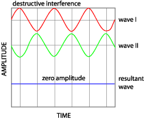
| Light waves that are exactly out of phase with
each other (by 180 degrees or p radians) undergo
destructive interference, as shown below, and their amplitudes cancel. In
intermediate cases, total amplitude is given by the vector resultant, and
intensity is given by the square of amplitude. | |
| |
| A simple illustration
of destructive interference | |
| Various experiments and instruments demonstrate
light interference phenomena. Some interference effects are possible only
with coherent sources (i.e., lasers), but many are produced by incoherent
light. Three of the best-known demonstrations of visible light
interference are Young's slits experiment, Newton's rings, and the
Fabry-Perot interferometer. These are described in most elementary optics
and physics texts. In all of these demonstrations, light from a source is split in some way to produce two similar wavefronts. The wavefronts are recombined with a variable path difference between them. Whenever the path difference is an integral number of half wavelengths (and if the wavefronts are of equal intensity), they cancel by destructive interference (i.e., an intensity minimum is produced). An intensity minimum is still produced if the interfering wavefronts are of differing amplitude; the result is just non-zero. When the path difference is an integral number of wavelengths, their intensities sum by constructive interference, and an intensity maximum is produced. | |
| Thin-Film
Interference | |
| Thin-film coatings also rely on the principles
of interference. Thin films are dielectric or metallic materials whose
thickness is comparable to, or less than, the wavelength of
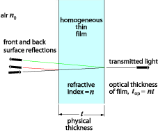
light. When a beam of light is incident on a thin film, some of the light will be reflected at the front surface, and some of light will be reflected at the rear surface, as shown in the figure below. The remainder will be transmitted. At this stage, we shall ignore multiple reflections. | |
| |
| Front= and
back-surface reflections for a thin film at near-normal
incidence | |
| The two reflected wavefronts can interfere with
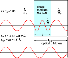
each other. This will depend on the ratio of optical thickness of the
material and the wavelength of the incident light (click here for
illustration). The optical thickness of an element is defined as the
equivalent vacuum thickness (i.e., the distance that light would travel in
vacuum in the same amount of time as it takes to traverse the optical
element of interest). In other words, the optical thickness of a piece of
material is the thickness of that material corrected for the apparent
change of wavelength passing through it. | |
| |
| An illustration of the
effects of lower light velocity in a dense medium. In this example, the
velocity of light is halved in the dense medium, n=n/ n0, and the optical thickness of the
medium is 2x the real thickness | |
| The optical thickness is given by top = t x n, where t is the physical thickness, and n is the ratio of the speed of light in the material
to the speed of light in vacuum: | |
 | |
| To a very good approximation, n is the refractive index of the
material. Returning to the thin film at normal incidence, the phase difference between the reflected wavefronts is given by (top/l) x 2p, where l is the wavelength of light, as usual, plus any phase differences caused by reflections at the surfaces. Clearly, if the wavelength of the incident light and the thickness of the film are such that a phase difference exists between reflections of p, then reflected wavefronts interfere destructively, and overall reflected intensity is a minimum. If the two reflections are of equal amplitude, then this amplitude (and hence intensity) minimum will be zero. In the absence of absorption or scatter, the principle of conservation of energy indicates all "lost" reflected intensity will appear as enhanced intensity in the transmitted beam. The sum of the reflected and transmitted beam intensities is always equal to the incident intensity. This important fact has been confirmed experimentally. Conversely, when the total phase shift between two reflected wavefronts is equal to zero (or multiples of 2p), then the reflected intensity will be a maximum, and the transmitted beam will be reduced accordingly. | |
| Back to Top | Previous Next |
| Optics Guide Copyright 2002 Melles Griot Inc. |

